power supply circuit
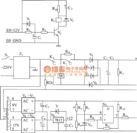
DZW75-48/50 (ii) 50 input circuit diagram
Published:2014/2/23 20:51:00 Author: | Keyword: DZW75-48/50 (ii) 50 input circuit diagram, | From:SeekIC

(1) 220 v AC voltage (50 hz) after Z1 line filter filter to AC overvoltage, undervoltage protection relay K2 contact, K2 contacts shall be closed up in normal working conditions, the AC voltage from 220 v AC current limiting resistor R4 R4 (after startup delay a period of time by K1 contact nipple), sent to the bridge rectifier rectifier power frequency, after smoothing filter and capacitor group about the output voltage of the DC 300 v, AC/DC power frequency conversion. R2 for discharge resistor. (2) the Z1 line filter is used to suppress and absorption power grid may have strong pulse interference with rectifier, improve the reliability of the rectifier. Line filter is good at the same time the common mode and differential mode of insertion loss, can effectively suppress the high frequency switch converter produced by reverse output of high frequency interference signals, the rectifier and isolation of power network, avoid mutual interference. (3) ac overvoltage, undervoltage protection circuit, ac 220 v voltage of line filter filter to the step-down transformer. (4) ac current limit delay circuit, ac voltage within the normal working range can be connected to the machine, ac power after the access time in auxiliary power supply, and after the construction of the auxiliary power supply by time delay, to make communication sub resistor, this paragraph of time is called ac current limit delay, it is being done by the alternating current limit delay circuit.
Reprinted Url Of This Article:
http://www.seekic.com/circuit_diagram/Power_Supply_Circuit/DZW75_48_50_ii_50_input_circuit_diagram.html
Print this Page | Comments | Reading(3)

Article Categories
power supply circuit
Amplifier Circuit
Basic Circuit
LED and Light Circuit
Sensor Circuit
Signal Processing
Electrical Equipment Circuit
Control Circuit
Remote Control Circuit
A/D-D/A Converter Circuit
Audio Circuit
Measuring and Test Circuit
Communication Circuit
Computer-Related Circuit
555 Circuit
Automotive Circuit
Repairing Circuit
Code: