power supply circuit
DUAL_SUPPLY
Published:2009/7/16 22:00:00 Author:Jessie | From:SeekIC

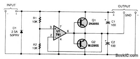
The key idea is that in a dual-supply powered circuit, ground is midway between the positive and negative supply voltages. Unfortunately, ordinary voltage regulators can't do the job. The reason is that they cart only source current, not sink it, and the ground terminal in a dual supply might have to either source or sink current, depending on which half of the load is drawing more current at the time. In the circuit, R1 and R2 divide the input voltage in half. Op amp U1 reproduces that voltage at the ground output terminal by making either Q1 or Q2 conduct as much as necessary. Capacitors Ct and C2 hold the output voltage steady when the load changes suddenly. Diode D1 is present to protect the circuit's input from reversed polarity by blowing the fuse of the main power supply. If your power supply has no fuse, place D1 in series with the circuit. That will afford the same protection with only slightly reduced regulation and voltage output.
Reprinted Url Of This Article:
http://www.seekic.com/circuit_diagram/Power_Supply_Circuit/DUAL_SUPPLY.html
Print this Page | Comments | Reading(3)

Article Categories
power supply circuit
Amplifier Circuit
Basic Circuit
LED and Light Circuit
Sensor Circuit
Signal Processing
Electrical Equipment Circuit
Control Circuit
Remote Control Circuit
A/D-D/A Converter Circuit
Audio Circuit
Measuring and Test Circuit
Communication Circuit
Computer-Related Circuit
555 Circuit
Automotive Circuit
Repairing Circuit
Code: