Battery Charger
±15_V_AND_5_V_CAR_BATTERY_SUPPLY
Published:2009/7/10 20:52:00 Author:May | From:SeekIC
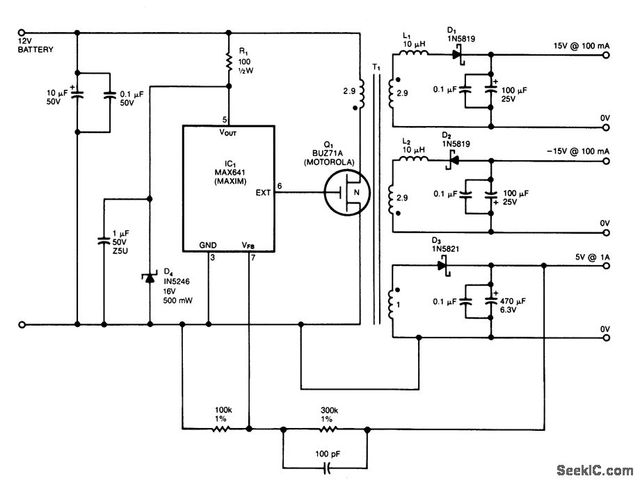

IC1is a switching regulator that generates a 45-kHz signal that drives the gate of MOSFET Q1.D1,D2, and D3 are Schottky diodes. The 5-V output is sensed as a reference; feedback to the chip turns offthe gate signal to Q1 if the voltage nses above 5 V.
T1 has Trifilar windings that assume about 2% regulation fr a 10-to 100-mA load change on the±15-V supplies, R1/D4 provide overvoltage protecti. T1 has a pnmary inductance ofabout 21 μH. Coreslze should allow 4-A peak currents. The turn ratios are 11 1/2 turns each for the 15-V supplies. 11 1/2 turns for the pnmary, and four turns for the 5-V secondary. The efficiency is about 75%.
Reprinted Url Of This Article:
http://www.seekic.com/circuit_diagram/Power_Supply_Circuit/Battery_Charger/±15_V_AND_5_V_CAR_BATTERY_SUPPLY.html
Print this Page | Comments | Reading(3)

Article Categories
power supply circuit
Amplifier Circuit
Basic Circuit
LED and Light Circuit
Sensor Circuit
Signal Processing
Electrical Equipment Circuit
Control Circuit
Remote Control Circuit
A/D-D/A Converter Circuit
Audio Circuit
Measuring and Test Circuit
Communication Circuit
Computer-Related Circuit
555 Circuit
Automotive Circuit
Repairing Circuit
Code: