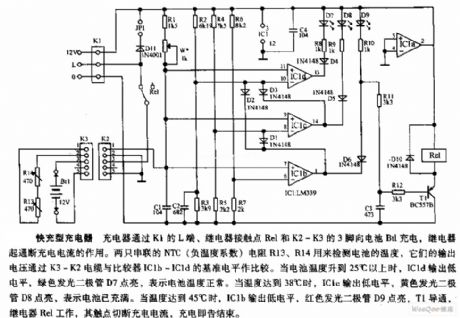
Battery Charger
Express charger circuit diagram
Published:2011/9/7 3:58:00 Author:Vicky | Keyword: Express charger circuit | From:SeekIC

Express charger circuit diagram
The charger charges Bt1via the Lend of K1, contact point Rel of relay, and pin 3 of K2-K3, while the relay acts to control on-off of the charging current. Two NTC (negative temperature coefficient) resistances R13 and R14 in serial are used to examine the temperature of battery. Their output voltage compares with the base level of comparators IC1b ~IC1d via wire cable K3 ~ K2. When the battery temperature rises to above 25℃, IC1d outputs low level, and the green luminous diode D7 is lighted to show that the battery temperature is normal. When the temperature rises to 38℃, IC1c outputs low level, and yellow luminous diode D8 is lighted to show that the battery is full charged. When the temperature rises to 45℃, IC1b outputs low level, the red luminous diode D9 is lighted, T1 is conducted, relay Rel starts working with its contact point cutting off the charging current, and the charging ends.
Reprinted Url Of This Article:
http://www.seekic.com/circuit_diagram/Power_Supply_Circuit/Battery_Charger/Express_charger_circuit_diagram.html
Print this Page | Comments | Reading(3)

Article Categories
power supply circuit
Amplifier Circuit
Basic Circuit
LED and Light Circuit
Sensor Circuit
Signal Processing
Electrical Equipment Circuit
Control Circuit
Remote Control Circuit
A/D-D/A Converter Circuit
Audio Circuit
Measuring and Test Circuit
Communication Circuit
Computer-Related Circuit
555 Circuit
Automotive Circuit
Repairing Circuit
Code: