power supply circuit
Automatic_shutdown_during_power_outages
Published:2009/7/24 4:25:00 Author:Jessie | From:SeekIC
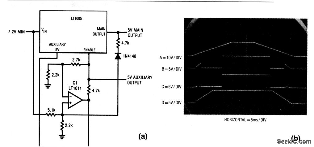
This circuit is useful when data bits must be transferred and stored into nonvolatile memory during power outages. The circuit takes advantage of the differing dropout voltages between the main and auxiliary outputs. When power is first applied, VIN (trace A in Fig. 9-6B) starts to rise (ramp up). The auxiliary output (trace D) follows this ramp action, and clamps at 5 V. During this interval, C1 monitors the difference between VIN and the 5-V auxiliary output. The resistor ratios are scaled so that the enable pin (trace B) is clamped until VIN is high enough to support main-output regulation. The small ramp segments that are visible at the enable pin are caused by the failure of C1 to clamp under a very low supply-voltage condition, and do not affect operation. The main output (trace C) comes up quickly. Because the auxiliary output precedes the main output, the auxiliary can be used to present conditions in the circuits being powered. When power falls below the threshold point, C1 pulls the enable pin low and forces the main output (trace C) off rapidly. However, the auxiliary output (trace D) maintains regulation after the main output is off. This allows the main output to be used as a logic signal to alert auxiliary-powered nonvolatile memory to store data. The amount of time that the auxiliary output will maintain regulation on power-down is controlled by the regulator tilter-capacitor size. The diode/4.7-kΩ combination provides regenerative action to ensure a clean turn-off for the main output.
Reprinted Url Of This Article:
http://www.seekic.com/circuit_diagram/Power_Supply_Circuit/Automatic_shutdown_during_power_outages.html
Print this Page | Comments | Reading(3)

Article Categories
power supply circuit
Amplifier Circuit
Basic Circuit
LED and Light Circuit
Sensor Circuit
Signal Processing
Electrical Equipment Circuit
Control Circuit
Remote Control Circuit
A/D-D/A Converter Circuit
Audio Circuit
Measuring and Test Circuit
Communication Circuit
Computer-Related Circuit
555 Circuit
Automotive Circuit
Repairing Circuit
Code: