power supply circuit
Automatic battery charger circuit with the voltage instruction
Published:2011/7/18 5:03:00 Author:TaoXi | Keyword: Automatic, battery charger, voltage instruction | From:SeekIC
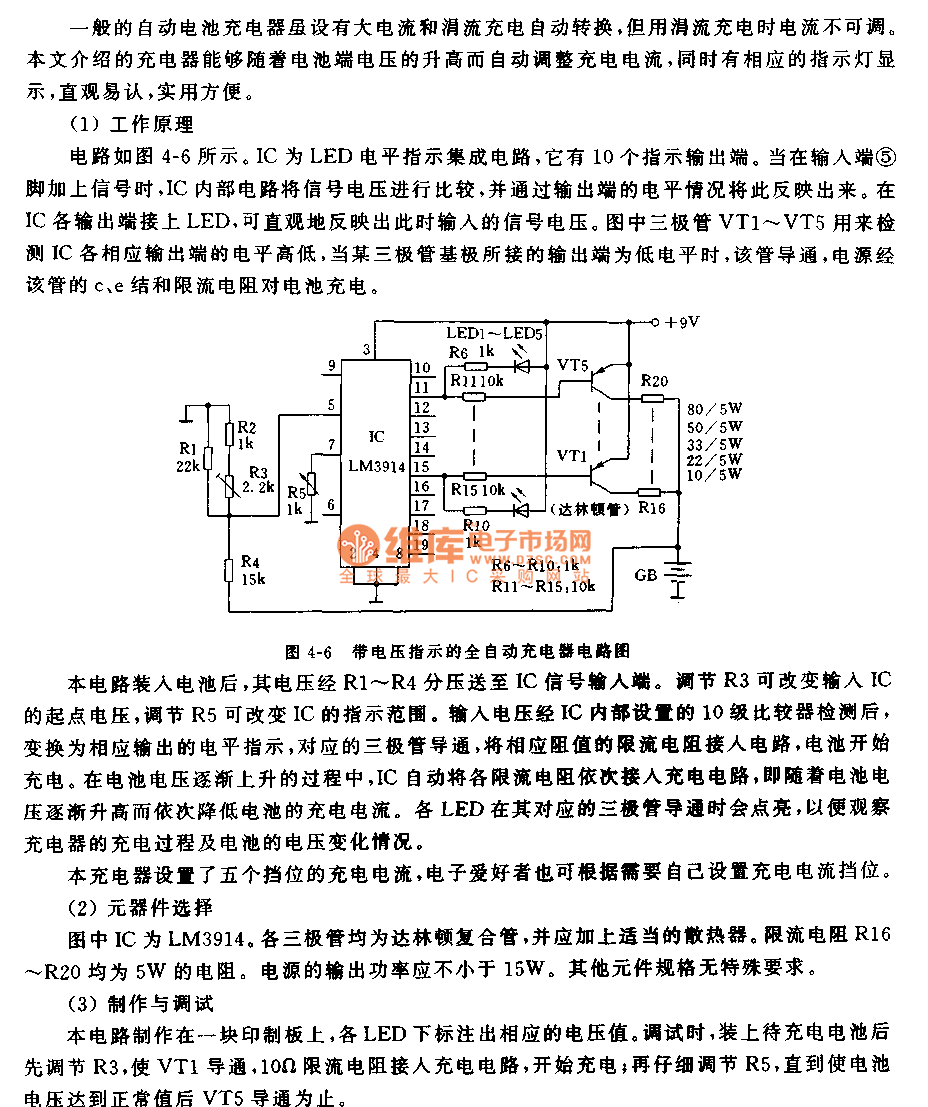
The circuit is as shown in figure 4-6. IC is the LED electrical level indication integrated circuit which has ten output instruction ports. When the signal is added on the pin-5 of the output port, the internal circuit of this IC will compare the signal voltage and report the result through the level situation of the output port. If you connect the LEDs with every port of the IC, the LED can intuitively report the input signal voltage. The transistors VT1-VT5 can be used to detect the levels of the IC's output ports. When the output port which is connected with the transistor base has the low level, this transistor will conduct, the power will charge the battery through the c, e junctions and the current limiting resistance.
Reprinted Url Of This Article:
http://www.seekic.com/circuit_diagram/Power_Supply_Circuit/Automatic_battery_charger_circuit_with_the_voltage_instruction.html
Print this Page | Comments | Reading(3)

Article Categories
power supply circuit
Amplifier Circuit
Basic Circuit
LED and Light Circuit
Sensor Circuit
Signal Processing
Electrical Equipment Circuit
Control Circuit
Remote Control Circuit
A/D-D/A Converter Circuit
Audio Circuit
Measuring and Test Circuit
Communication Circuit
Computer-Related Circuit
555 Circuit
Automotive Circuit
Repairing Circuit
Code: