power supply circuit
555 positive voltage converting to 5v power supply circuit
Published:2011/7/24 4:06:00 Author:Lucas | Keyword: 555 positive voltage , 5v power supply | From:SeekIC
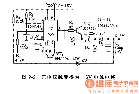
The 555 and R1, C1, VT1 and other components in Figure 9-2 form a multivibrator with the oscillation frequency being determined by R1, C1, R3 . C1 charges through R1, when the the potential of pin 6 charges to above 2/3 VDD of the threshold level, the 555 resets, pin 3 is at low level. DW is a Zener diode, when the negative output voltage is prompted to turn on D5, VT1 remains cut-off state. When the load current makes C1 discharge to a certain extent, D5 is deadline, and VT1 is turned on, then C1 begins to charge. The oscillation frequency of 555 changes with a certain load. Power load adjusted rate is about 1.5%.
Reprinted Url Of This Article:
http://www.seekic.com/circuit_diagram/Power_Supply_Circuit/555_positive_voltage_converting_to_5v_power_supply_circuit.html
Print this Page | Comments | Reading(3)

Article Categories
power supply circuit
Amplifier Circuit
Basic Circuit
LED and Light Circuit
Sensor Circuit
Signal Processing
Electrical Equipment Circuit
Control Circuit
Remote Control Circuit
A/D-D/A Converter Circuit
Audio Circuit
Measuring and Test Circuit
Communication Circuit
Computer-Related Circuit
555 Circuit
Automotive Circuit
Repairing Circuit
Code: