power supply circuit
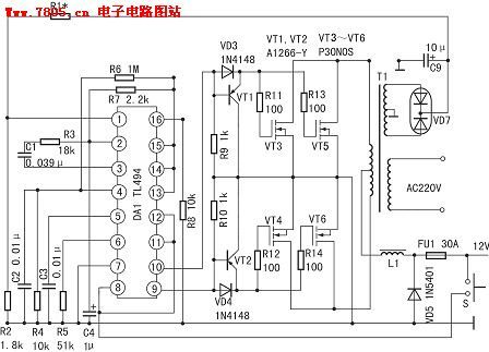
400W inverter circuit
Published:2011/7/18 21:42:00 Author:TaoXi | Keyword: 400W, inverter | From:SeekIC


The voltage stabilization sampling and error amplification system is composed of the pin-1 and pin-2, the positive phase input port pin-1 inputs the 15V DC voltage which is rectified and output by the inverter sub-sampling winding, and this 15V DC voltage is divided by R1 and R2 to supply the 4.7~5.6V sampling voltage to the inverter. The reverse phase input port pin-2 inputs the 5V reference voltage which is output by the pin-14. When the output voltage decreases, the voltage of pin-1 decreases too, the error amplifier outputs the low level to rise the output voltage through the PWM circuit. The voltage of pin-1 is 5.4V, the voltage of pin-2 is 5.0V, the voltage of pin-3 is 0.06V. At this time the output AC voltage is 235V (square wave voltage).
Reprinted Url Of This Article:
http://www.seekic.com/circuit_diagram/Power_Supply_Circuit/400W_inverter_circuit.html
Print this Page | Comments | Reading(3)

Article Categories
power supply circuit
Amplifier Circuit
Basic Circuit
LED and Light Circuit
Sensor Circuit
Signal Processing
Electrical Equipment Circuit
Control Circuit
Remote Control Circuit
A/D-D/A Converter Circuit
Audio Circuit
Measuring and Test Circuit
Communication Circuit
Computer-Related Circuit
555 Circuit
Automotive Circuit
Repairing Circuit
Code: