power supply circuit
2_W_WITH_LOW_PASS_FILTER
Published:2009/7/16 6:32:00 Author:Jessie | From:SeekIC
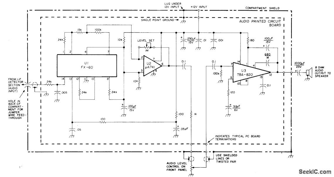
Developed for use in dual-conversion amateur receiver. Detected audio is passed through active low-pass filter-opamp arrangement U1-U2 and further amplified by 2-W audio amplifier U3. Simple voltage-divider circuit on pin 3 of U2 establishes artificial ground for U1 and U2. Low-pass rolloff starts at 2500 Hz, with about 20-dB attenuation of higher audio frequencies. IF heterodyne hiss is greatly attenuated and overall S/N ratio of receiver enhanced. Level-set 1-megohm pot between pins 2 and 7 of U2 establishes output gain for U1 and U2 together at about 0.8.-M. A. Chapman, High-Performance 20-Meter Receiver with Digital Frequency Readout, Ham Radio, Oct. 1977, p 48-61.
Reprinted Url Of This Article:
http://www.seekic.com/circuit_diagram/Power_Supply_Circuit/2_W_WITH_LOW_PASS_FILTER.html
Print this Page | Comments | Reading(3)

Article Categories
power supply circuit
Amplifier Circuit
Basic Circuit
LED and Light Circuit
Sensor Circuit
Signal Processing
Electrical Equipment Circuit
Control Circuit
Remote Control Circuit
A/D-D/A Converter Circuit
Audio Circuit
Measuring and Test Circuit
Communication Circuit
Computer-Related Circuit
555 Circuit
Automotive Circuit
Repairing Circuit
Code: