power supply circuit
0.6-1.5V/2-6A regulated voltage circuit
Published:2011/5/5 3:03:00 Author:muriel | Keyword: 0.6-1.5V/2-6A, regulated voltage circuit | From:SeekIC
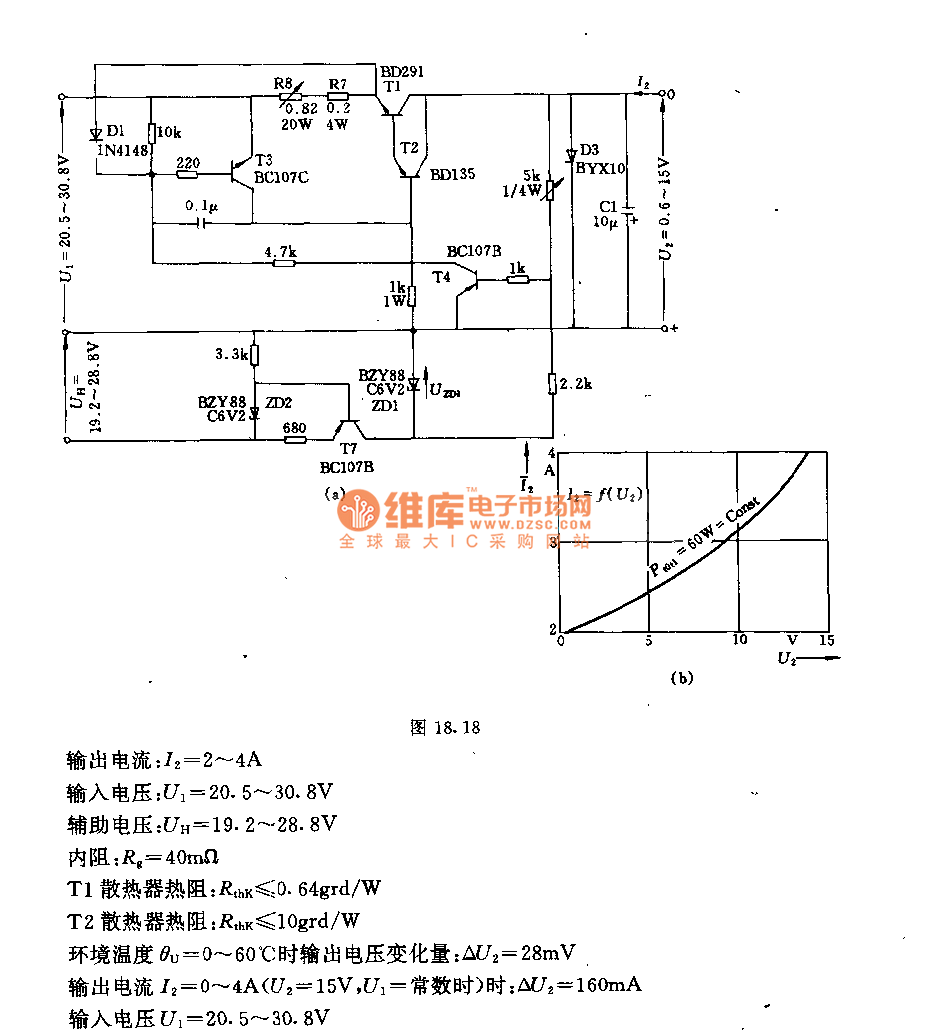
When it uses the auxiliary power supply Uh, Itcanregulate output voltage low to U2 = 0.6 V(FIG. A). After Adjusted the potentiometer R8, itcan changethe load current of limitation whichmakes transistor loss powerless than its maximum allowable (FIG. B). The circuit of the main technical data:Technology data of the circuit: output voltage:U2=0.6V~15V output current:I2=2A~4A input voltage:U1=20.5V~30.8V internal resistance:Rg=40mΩ T1Radiator thermal resistance:Rthk≤0.64grd/W T2Radiator thermal resistance:Rthk≤10grd/W when ambient temperatureθu=0°C~60°C output voltage variable quantity: ΔU2=28mV when output current I2=0~4A(U1=constant,U2=15V), ΔU2=160mV input voltage U1=20.5~30.8V
Reprinted Url Of This Article:
http://www.seekic.com/circuit_diagram/Power_Supply_Circuit/06_15V_2_6A_regulated_voltage_circuit.html
Print this Page | Comments | Reading(3)

Article Categories
power supply circuit
Amplifier Circuit
Basic Circuit
LED and Light Circuit
Sensor Circuit
Signal Processing
Electrical Equipment Circuit
Control Circuit
Remote Control Circuit
A/D-D/A Converter Circuit
Audio Circuit
Measuring and Test Circuit
Communication Circuit
Computer-Related Circuit
555 Circuit
Automotive Circuit
Repairing Circuit
Code: