Measuring and Test Circuit
ac_WATTS_CALCULATOR
Published:2009/6/17 21:55:00 Author:May | From:SeekIC


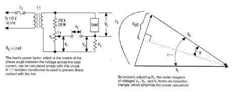
The method basically consists of determining the power factor of the load-the cosine of the phase angle between the voltage across the load and the load circuit. Using a simple circuit, that an-gle can be calculated quite simply.This circuit uses a 1:1 isolation transformer to prevent direct contact with the line. It is wise to proceed with caution whenever voltages of this magnitude are utilized in a test setup, even though the voltages that will be measured are usually below 1 V.RS is a circuit-sense resistor and Rr is a multi-turn potentiometer. The voltage across Rr is ap-proximately 0.5% of the line voltage, which should be sufficient for most applications.Rr is adjusted so that |Vr|=|Vs|; then Vd is measured. In the vector diagram according to Kirchhoff's voltage law, Vs,Vd, and Vr form a triangle, which becomes isosceles by adjusting Rr. Vs is in phase with the load current and Vr is essentially in phase with the load voltage.The power delivered to the load can be calculated as follows:
Reprinted Url Of This Article:
http://www.seekic.com/circuit_diagram/Measuring_and_Test_Circuit/ac_WATTS_CALCULATOR.html
Print this Page | Comments | Reading(3)

Article Categories
power supply circuit
Amplifier Circuit
Basic Circuit
LED and Light Circuit
Sensor Circuit
Signal Processing
Electrical Equipment Circuit
Control Circuit
Remote Control Circuit
A/D-D/A Converter Circuit
Audio Circuit
Measuring and Test Circuit
Communication Circuit
Computer-Related Circuit
555 Circuit
Automotive Circuit
Repairing Circuit
Code: