Measuring and Test Circuit
ULTRA_SIMPLE_RS232_TESTER
Published:2009/7/12 21:05:00 Author:May | From:SeekIC

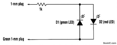
The tester consists of no more than a two-color LED (or a red and a green LED connected in anti-parallel) in series with a 1-kΩ resistor. The free ends of the resistor and the LEDs should preferably be terminated in 1-mm plugs. One of the free ends should be covered in green sleeving, or use a green 1-mm plug. This is touched on pin 7 (signal ground) of the connector under test. The other end is touched on each pin to be tested, in turn. The LED (or LED pair) is connected so that a positive voltage emits a red glow and a negative voltage causes a green glow. Sometimes, an RS232 input will be found that has an internally connected pull-up to drive a particular default RS232 level when unconnected. Although this will cause the tester to glow as if the pin were an output, it will do so with markedly less brightness. Bearing this in mind, the tester can be used to diagnose most RS232 problems at the electrical level.
Reprinted Url Of This Article:
http://www.seekic.com/circuit_diagram/Measuring_and_Test_Circuit/ULTRA_SIMPLE_RS232_TESTER.html
Print this Page | Comments | Reading(3)

Article Categories
power supply circuit
Amplifier Circuit
Basic Circuit
LED and Light Circuit
Sensor Circuit
Signal Processing
Electrical Equipment Circuit
Control Circuit
Remote Control Circuit
A/D-D/A Converter Circuit
Audio Circuit
Measuring and Test Circuit
Communication Circuit
Computer-Related Circuit
555 Circuit
Automotive Circuit
Repairing Circuit
Code: