Measuring and Test Circuit
UHF_MOVEMENT_DETECTOR
Published:2009/7/9 21:26:00 Author:May | From:SeekIC


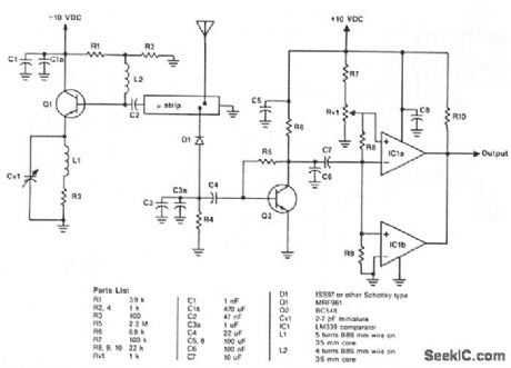
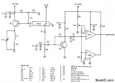
The oscillator is a standard UHF design which delivers about 10 mW at 1.2 GHz. R1 and R2 bias the base of Q1 to 1.2 V via L2. Collector current is set by R3 to about 30 mA. C2 couples the base of Q1 to the stripline circuit. Tuning is provided by CV1, and C1 plus C1a decouple the collector. R2 and R3 are not decoupled, since this could cause instability.Q2 is a simple one-transistor amplifier. C4 and C7 reduce gain below 1.5 and above 100 Hz; the remaining band of frequencies is amplified and passed on to the level detector. Two comparators of IC1 provide level detection. The trigger voltage is set by R7, Rv1, R8, and R9; it is adjustable from 8 to 60 mV by Rv1.Positive voltage swings above the trigger level cause the IC1a output to become low, while negative swings cause IC1b to become low. C8 decouples IC1 from the power supply, and R10 is a pull-up resistor for the open collector output of IC1.
Reprinted Url Of This Article:
http://www.seekic.com/circuit_diagram/Measuring_and_Test_Circuit/UHF_MOVEMENT_DETECTOR.html
Print this Page | Comments | Reading(3)

Article Categories
power supply circuit
Amplifier Circuit
Basic Circuit
LED and Light Circuit
Sensor Circuit
Signal Processing
Electrical Equipment Circuit
Control Circuit
Remote Control Circuit
A/D-D/A Converter Circuit
Audio Circuit
Measuring and Test Circuit
Communication Circuit
Computer-Related Circuit
555 Circuit
Automotive Circuit
Repairing Circuit
Code: