Measuring and Test Circuit
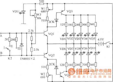
The survey meter circuit of LED display
Published:2011/6/6 21:38:00 Author:qqtang | Keyword: survey meter, LED display | From:SeekIC

In the figure is the survey meter circuit of LED display, which can play a big part in solving some physical experiment problems. A and B are the input terminals of the current under test. Transistors of VQ1, VQ3 and VQ2, VQ4 form the coupling DC amplifier of common emitting poles on the two sides, respectively, and the LED of VD1~VD5 and VD6~VD10 are the display elements of two directions. When the current flows to B from A, the transistor of VQ2 cuts down its basic pole LEV, the working voltage is going down and VQ4 is blocked with it.
Reprinted Url Of This Article:
http://www.seekic.com/circuit_diagram/Measuring_and_Test_Circuit/The_survey_meter_circuit_of_LED_display.html
Print this Page | Comments | Reading(3)

Article Categories
power supply circuit
Amplifier Circuit
Basic Circuit
LED and Light Circuit
Sensor Circuit
Signal Processing
Electrical Equipment Circuit
Control Circuit
Remote Control Circuit
A/D-D/A Converter Circuit
Audio Circuit
Measuring and Test Circuit
Communication Circuit
Computer-Related Circuit
555 Circuit
Automotive Circuit
Repairing Circuit
Code: