Measuring and Test Circuit
The power test circuit
Published:2011/5/22 0:50:00 Author:Borg | Keyword: power test | From:SeekIC

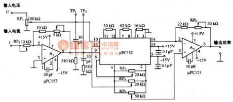
The figure is a power test circuit. Power is equal to voltage multiplies current. The circuit is formed by a multiplier of μPCl32. The input voltage is imposed on the 10 pin interface through RP1(electricity distributor), and the input current is imposed on the 9-pin of μPCl32 after being magnified. The power is delivered out by A2 after the input current multiplies the input voltage. By the way, the max voltage on the 9 and 10 pins can be higher than ±lOV, which could be set by the resistances of RP1 and RP2.When adjusting, connect the 10-pin of the voltage input terminal with the ground at first.
Reprinted Url Of This Article:
http://www.seekic.com/circuit_diagram/Measuring_and_Test_Circuit/The_power_test_circuit.html
Print this Page | Comments | Reading(3)

Article Categories
power supply circuit
Amplifier Circuit
Basic Circuit
LED and Light Circuit
Sensor Circuit
Signal Processing
Electrical Equipment Circuit
Control Circuit
Remote Control Circuit
A/D-D/A Converter Circuit
Audio Circuit
Measuring and Test Circuit
Communication Circuit
Computer-Related Circuit
555 Circuit
Automotive Circuit
Repairing Circuit
Code: