Measuring and Test Circuit
The Typical Circuit Diagram of Monolithick Color Scanner (LM9832)
Published:2011/9/8 6:19:00 Author:Ariel Wang | Keyword: Typical , Monolithick, scanner | From:SeekIC
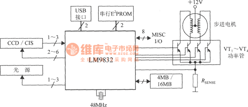
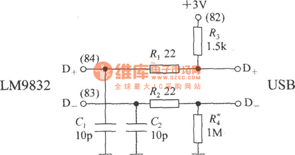
The circuit is constituted by the LM9832 typical single color scanner . RSENSE is the stepper motor current sense resistor. VT1 ~ VT4 are external drive tubes. LM9832 uses a USB interface.The data receives and sends through the D + and D-pins. These data is 3V differential signal. The circuit between LM9832 D + , D-pins-chip and the color scanner with a USB connector could be seen as the chart. R1 and R2 are two data lines limiting resistor. C1 and C2 are the capacitors to eliminate noise.R3 is the pull-up resistor , R4 is the pull-down resistor.
Reprinted Url Of This Article:
http://www.seekic.com/circuit_diagram/Measuring_and_Test_Circuit/The_Typical_Circuit_Diagram_of_Monolithick_Color_Scanner_LM9832.html
Print this Page | Comments | Reading(3)

Article Categories
power supply circuit
Amplifier Circuit
Basic Circuit
LED and Light Circuit
Sensor Circuit
Signal Processing
Electrical Equipment Circuit
Control Circuit
Remote Control Circuit
A/D-D/A Converter Circuit
Audio Circuit
Measuring and Test Circuit
Communication Circuit
Computer-Related Circuit
555 Circuit
Automotive Circuit
Repairing Circuit
Code: