Measuring and Test Circuit
TRANSISTOR_CHECKER
Published:2009/6/17 22:01:00 Author:May | From:SeekIC


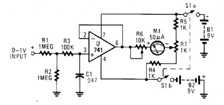
The circuit is built around a 741 general-purpose op amp that is configured as a voltage follower; with the components shown, the op amp has a voltage gain of one. The output of the 741 is used to drive a 50-pA meter rnovement. Potentiometer R7 is used to zero the meter and R6 sets the meter's full-scale reading.
Calibrating the meter is a snap. With no input applied to the circuit, set R6 to mid-position and adjust R7 to zero the meter. Once that is done, apply a positive 1-Vdc voltage to the input and adjust R6 for a full-scale reading. The voltmeter can be adjusted to read both positive and negative voltages by adjusting R7 for a center scale reading at the meter's zero position and a positive 1-V reading at the meter's full-scale position.
Reprinted Url Of This Article:
http://www.seekic.com/circuit_diagram/Measuring_and_Test_Circuit/TRANSISTOR_CHECKER.html
Print this Page | Comments | Reading(3)

Article Categories
power supply circuit
Amplifier Circuit
Basic Circuit
LED and Light Circuit
Sensor Circuit
Signal Processing
Electrical Equipment Circuit
Control Circuit
Remote Control Circuit
A/D-D/A Converter Circuit
Audio Circuit
Measuring and Test Circuit
Communication Circuit
Computer-Related Circuit
555 Circuit
Automotive Circuit
Repairing Circuit
Code: