Measuring and Test Circuit
STEREO_BALANCE_METER
Published:2009/6/25 21:44:00 Author:Jessie | From:SeekIC

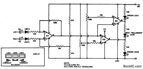
Outputs from each channel are fed to the two inputs of IC1 conrfected as a differential amplifier. IC2 and 3 are driven by the output of IC1. Output of IC1 is connected to the nonin-verting inputs of IC2 and 3. If the output of IC1 approaches the supply rail, the outputs of ICs 2 and 3 will also go high, illuminating LED3. This would happen if the right channel were dominating. If the left channel was dominant, the outputs of ICs 2 and 3 would be low, il-luminating LED1. If the two channels are equal in amplitude, the outputs of ICs 2 and 3 would be high and low respectively, lighting up LED2.
Reprinted Url Of This Article:
http://www.seekic.com/circuit_diagram/Measuring_and_Test_Circuit/Stereo_balance_meter.html
Print this Page | Comments | Reading(3)

Article Categories
power supply circuit
Amplifier Circuit
Basic Circuit
LED and Light Circuit
Sensor Circuit
Signal Processing
Electrical Equipment Circuit
Control Circuit
Remote Control Circuit
A/D-D/A Converter Circuit
Audio Circuit
Measuring and Test Circuit
Communication Circuit
Computer-Related Circuit
555 Circuit
Automotive Circuit
Repairing Circuit
Code: