Measuring and Test Circuit
SINGLE_CHIP_DIGITAL_VOLTMETER
Published:2009/6/18 23:04:00 Author:May | From:SeekIC

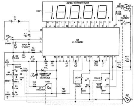
This 4 1/2-digit DVM circuit is built around a Maxim ICL7129ACPL A/D converter and LCD driver. An ICL8069 CCZR 1.2-V band-gap reference diode is used for a voltage reference. S2a-b-c select one of four ranges up to 200 V (maximum). The meter also has a piezoelectric buzzer for continuity testing. S3 selects either DVM or continuity. Crystal 1 can be changed to 100 kHz if maximum rejection of 50 Hz is desired. The crystal normally provides 120 kHz for best 60-Hz rejection. This is caused by the dual-slope conversion technique used in IC1.
Reprinted Url Of This Article:
http://www.seekic.com/circuit_diagram/Measuring_and_Test_Circuit/SINGLE_CHIP_DIGITAL_VOLTMETER.html
Print this Page | Comments | Reading(3)

Article Categories
power supply circuit
Amplifier Circuit
Basic Circuit
LED and Light Circuit
Sensor Circuit
Signal Processing
Electrical Equipment Circuit
Control Circuit
Remote Control Circuit
A/D-D/A Converter Circuit
Audio Circuit
Measuring and Test Circuit
Communication Circuit
Computer-Related Circuit
555 Circuit
Automotive Circuit
Repairing Circuit
Code: