Measuring and Test Circuit
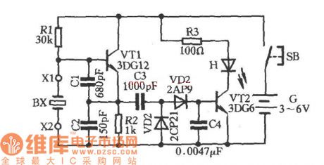
Quartz Crystal Selection Circuit Diagram
Published:2011/6/18 10:18:00 Author:Vicky | Keyword: Quartz Crystal Selection | From:SeekIC

As shown in the above picture, BX is a Quartz Crystal (also called crystal oscillator) under test. Plug it into sockets X1 and X2, and press button SB. If BX is good, the oscillator composed of triode VT1, capacitances C1 and C2 works. The oscillator signal was sent from VT1 emitter, and coupled to VD2 via C3 to process detection and C4 filtering. It then becomes direct current and is sent to VT2 base electrode to make VT2 conducted and luminous diode H give out light, which is an indication that the quartz crystal is good. If H doesn’t give out light, then the quartz crystal is bad. By changing the capacitance value of C1 and C2 appropriately, it can be used to test quartz crystals of different frequency.
Reprinted Url Of This Article:
http://www.seekic.com/circuit_diagram/Measuring_and_Test_Circuit/Quartz_Crystal_Selection_Circuit_Diagram.html
Print this Page | Comments | Reading(3)

Article Categories
power supply circuit
Amplifier Circuit
Basic Circuit
LED and Light Circuit
Sensor Circuit
Signal Processing
Electrical Equipment Circuit
Control Circuit
Remote Control Circuit
A/D-D/A Converter Circuit
Audio Circuit
Measuring and Test Circuit
Communication Circuit
Computer-Related Circuit
555 Circuit
Automotive Circuit
Repairing Circuit
Code: