Measuring and Test Circuit
PICOAMPERE_MEASURER
Published:2009/7/16 2:48:00 Author:Jessie | From:SeekIC

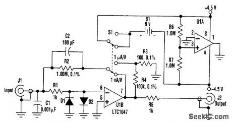
Many times, the need arises to measure current below 1 μA. The circuit shown turns any voltmeter into a picoammeter with scales of 1 μA/V and 1 μA/V. With a 3 1/2-digit voltmeter with a resolution of 1 mV, the readout will be in picoamperes or nanoamperes. In addition, it can be attached to an oscilloscope. The frequency response is about 1 kHz for the 1 μA/V setting and 150 Hz for 1 μA/V.U1B forms a transimpedance amplifier. With S1 in the position shown, the transimpedance is 1MΩ.In the other position, a gain of 1000 is added, to make the total transimpedance 1GΩ. R1, C1, D1, and D2 protect the input from high voltages, and R5 isolates the op amp's output from any load capacitance. The op amp's input current and voltage offset must be low for this circuit to work. In this case, a Linear Technology LTC1047 was used. It has a nominal input bias current of ±5 pA and a V0S of ±3μV at room temperature. U1A is used to split the 9-V battery into positive and negative supplies. The total current is essentially the supply current of the op amps. For the prototype, the total current measured for the LTC1047 was <100 μA, so a standard 9-V battery should last six months if you forget to turn it off.
Reprinted Url Of This Article:
http://www.seekic.com/circuit_diagram/Measuring_and_Test_Circuit/PICOAMPERE_MEASURER.html
Print this Page | Comments | Reading(3)

Article Categories
power supply circuit
Amplifier Circuit
Basic Circuit
LED and Light Circuit
Sensor Circuit
Signal Processing
Electrical Equipment Circuit
Control Circuit
Remote Control Circuit
A/D-D/A Converter Circuit
Audio Circuit
Measuring and Test Circuit
Communication Circuit
Computer-Related Circuit
555 Circuit
Automotive Circuit
Repairing Circuit
Code: