Measuring and Test Circuit
PC_POWER_PINCHER
Published:2009/7/12 21:43:00 Author:May | From:SeekIC

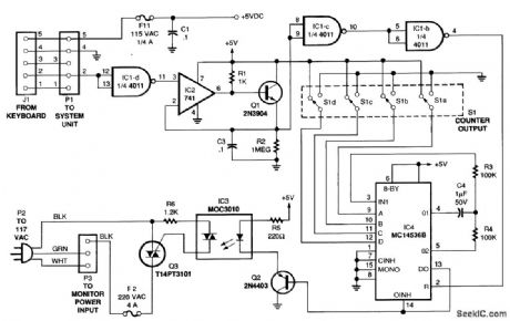
The figure is a diagram of the circuit, in which a low-frequency oscillator continually drives the input of a multistage binary counter. Whenever the count reaches the setting selected by DIP switch S1, the circuit turns triac Q3 off, thereby interrupting the flow of 120-Vac to the monitor. A keyboard-monitoring circuit keeps the video monitor powered up during active use by resetting the counter every time a key is pressed. As long as a keypress occurs before the time delay expires, the counter keeps resetting. Hence, it never times out, and the monitor continues to receive power. When the computer turns on, a routing in its basic input/output system (BIOS) polls the keyboard. The keyboard, in turn, sends a series of data pulses back to the microprocessor to indicate its status. The data line is normally high (+5 V), and the pulses are low-going transitions. The first stage of the power pincher inverts the sense of the logic to normally low with high-going transitions.
Reprinted Url Of This Article:
http://www.seekic.com/circuit_diagram/Measuring_and_Test_Circuit/PC_POWER_PINCHER.html
Print this Page | Comments | Reading(3)

Article Categories
power supply circuit
Amplifier Circuit
Basic Circuit
LED and Light Circuit
Sensor Circuit
Signal Processing
Electrical Equipment Circuit
Control Circuit
Remote Control Circuit
A/D-D/A Converter Circuit
Audio Circuit
Measuring and Test Circuit
Communication Circuit
Computer-Related Circuit
555 Circuit
Automotive Circuit
Repairing Circuit
Code: