Measuring and Test Circuit
MULTICONDUCTOR_SHORT_OPEN_CABLE_TESTER
Published:2009/7/15 23:38:00 Author:Jessie | From:SeekIC

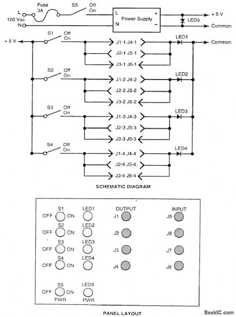
Frequent or regular testing of multiconductor cables terminated in multipin conductors can be a tedious, if not impossible, task. This is especially true if the cables must be tested for both open and short circuits for all of the various combinations of conductors. The inexpensive circuit shown in the figure simplifies the task. In operation, a pair of connectors is selected to match the pair of connec-tors installed on each of the cables to be tested. A single-pole/single-throw (SPST) toggle switch is provided for each conductor of whichever cable in the system has the greatest number of conductors. One conductor of each of the output connectors is connected in parallel to the anode of an LED.One LED is required for each conductor of the cable that has the greatest number of conductors. The cathodes of the LEDs are tied together and connected to the common side of the 5-V power supply.At the beginning of a test, all of the switches are turned off. First, one turns on power switch S5 and verifies that LED5 illuminates. Then one turns on switches S1 through S4, one at a time. Only the LED corresponding to the switch that is on should illuminate. An open conductor in the test cable is indicated if the corresponding LED is not illuminated. A short circuit is indicated if any other than the corresponding LED is illuminated.
Reprinted Url Of This Article:
http://www.seekic.com/circuit_diagram/Measuring_and_Test_Circuit/MULTICONDUCTOR_SHORT_OPEN_CABLE_TESTER.html
Print this Page | Comments | Reading(3)

Article Categories
power supply circuit
Amplifier Circuit
Basic Circuit
LED and Light Circuit
Sensor Circuit
Signal Processing
Electrical Equipment Circuit
Control Circuit
Remote Control Circuit
A/D-D/A Converter Circuit
Audio Circuit
Measuring and Test Circuit
Communication Circuit
Computer-Related Circuit
555 Circuit
Automotive Circuit
Repairing Circuit
Code: