Measuring and Test Circuit
MILLIOHM_TESTER
Published:2009/7/16 2:40:00 Author:Jessie | From:SeekIC

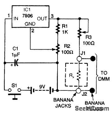
The milliohm adapter circuit is powered from a 9-V battery. A resistor to be tested (RX) is connected across banana jacks J1 and J2, and a pair of banana plugs, connected directly to J1 and J2, is plugged into the voltage input jacks of a DMM. Switch S1 applies battery power to 7806 voltage regulator IC1. Capacitor C1 removes voltage transients. Resistors R1 and R2 form a voltage divider for the GROUND pin of IC1. Potentiometer R2 trims IC1's output voltage to exactly 6 Vdc. Potentiometer R3 sets the output current through RX, to 100mA. Because R3 is a relatively large resistance compared to RX, the error introduced by different values of RX, (1 mΩ to 1Ω), the effect it will have on the 100-mA current source, is below 2 percent.
Reprinted Url Of This Article:
http://www.seekic.com/circuit_diagram/Measuring_and_Test_Circuit/MILLIOHM_TESTER.html
Print this Page | Comments | Reading(3)

Article Categories
power supply circuit
Amplifier Circuit
Basic Circuit
LED and Light Circuit
Sensor Circuit
Signal Processing
Electrical Equipment Circuit
Control Circuit
Remote Control Circuit
A/D-D/A Converter Circuit
Audio Circuit
Measuring and Test Circuit
Communication Circuit
Computer-Related Circuit
555 Circuit
Automotive Circuit
Repairing Circuit
Code: