Measuring and Test Circuit
METER_TESTER
Published:2009/7/10 2:13:00 Author:May | From:SeekIC

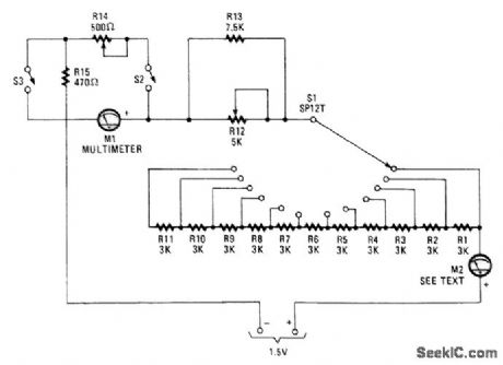
This unit uses switches and resistors to provide a number of current ranges. It allows you to test most of the meters available at surplus outlets, and without damaging the sensitive movements when you have no idea of internal resistance or full-scale current of the unit.
M1 is a multimeter set to measure current, and M2 is the meter-under-test. Starting with S1 set at the maximum resistance and S2 open, decrease the resistance setting of S1, fine tuning with R12, until M2 reads full scale. Then, read Ml. It will tell you the full-scale current for the unknown meter. As the meters are connected in series, the same current flows through both.
Now, close S2 and adjust R14 and R15 until M2 reads exactly mid-scale and M1 reads the same cur-rent as determined earlier to be the maximum current for M2. Half the current is flowing in M2 and half is going through R14 and R15. The voltage drop is the same across the meter and R14 and R15, because they're in parallel. Thus, the sum of the resistance of R14 and R15 is the same as the internal resistance of meter M2.
If the internal resistance of M2 is less than 470Ω, set R14 at maximum resistance and close S3. Read-just R14. Both R14 and R12 should be linear-taper potentiometers.
Reprinted Url Of This Article:
http://www.seekic.com/circuit_diagram/Measuring_and_Test_Circuit/METER_TESTER.html
Print this Page | Comments | Reading(3)

Article Categories
power supply circuit
Amplifier Circuit
Basic Circuit
LED and Light Circuit
Sensor Circuit
Signal Processing
Electrical Equipment Circuit
Control Circuit
Remote Control Circuit
A/D-D/A Converter Circuit
Audio Circuit
Measuring and Test Circuit
Communication Circuit
Computer-Related Circuit
555 Circuit
Automotive Circuit
Repairing Circuit
Code: