Measuring and Test Circuit
MAGNETIC_FIELD_METER_
Published:2009/7/13 6:05:00 Author:May | From:SeekIC

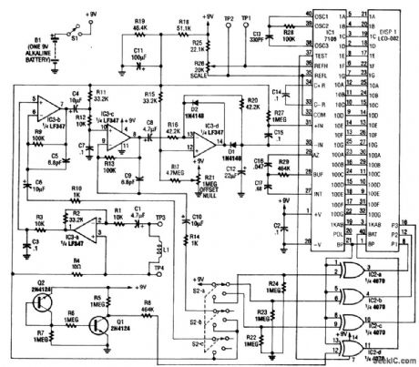
The meter's 12-turn field pickup is integrated into the unit's circuit board. For remote sensing, an external field coil probe can be used. The magnetic field picked up by the coil appears as a voltage, which is proportional to field strength and frequency at the input of a cascaded amplifier IC3-a, IC3-b, and IC3-c. With a first-stage amplifier gain of 3.3 set by R12 to R10, the overall sensitivity is 100 μV/μT, or 100 mV/mT. The meter sensitivity is nominally 2 V full scale, leading to the lowestlevel sensitivity of 20 mT full scale. Op amp IC3-a amplifies the signal to a normalized level of 100 μV/μT. The voltage is further amplified by 1, 100, or 10,000 by IC3-b and IC3-c. The three amplifier stages provide the ranges of 2 mT,200 μT, and 2 μT (full scale). Components R3 and C3 and R12 and C7 establish a frequency rolloff characteristic that compensates for the frequency-proportional sensitivity of the pickup coil, and set the 20-kHz cutoff point. IC3-d is a precision rectifier and peak detector. Its output drives IC1, a combination analog-to-digital (A/D) converter and LCD driver. Components R25 to R29 and C13 to C17 are used by IC1 to set display-update times, clock generation, and reference voltages. The decimal points are driven by IC2, as determined by range-select switch S2. Transistors Q1 and Q2 serve as a low-batterydetector, and turn on the battery annunciator in the LCD when the battery voltage drops below 7 V.
Reprinted Url Of This Article:
http://www.seekic.com/circuit_diagram/Measuring_and_Test_Circuit/MAGNETIC_FIELD_METER_.html
Print this Page | Comments | Reading(3)

Article Categories
power supply circuit
Amplifier Circuit
Basic Circuit
LED and Light Circuit
Sensor Circuit
Signal Processing
Electrical Equipment Circuit
Control Circuit
Remote Control Circuit
A/D-D/A Converter Circuit
Audio Circuit
Measuring and Test Circuit
Communication Circuit
Computer-Related Circuit
555 Circuit
Automotive Circuit
Repairing Circuit
Code: