Measuring and Test Circuit
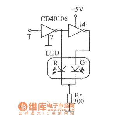
Logic level test circuit diagram
Published:2011/5/3 0:49:00 Author:Ecco | Keyword: logic level, test | From:SeekIC

Logic level test circuit is shown as the chart. CD40106 is six inverter with a Schmitt trigger, T is the probe, when the T contacting point is 0 , after driven by inverting, LED-R emits red light, LED-G is off; when the detection point is 1 , LED-R reverse bias is off, but after being twice reversed, LED-G emits green light; when the T detects CP pulse, the two tube is lit alternately. As the clock pulse frequency is higher, while it is higher than 24Hz, the two tubes seem like being lit simultaneously because of the visual pictures effect of eyes, rather than flash alternately, the light is orange.
Reprinted Url Of This Article:
http://www.seekic.com/circuit_diagram/Measuring_and_Test_Circuit/Logic_level_test_circuit_diagram.html
Print this Page | Comments | Reading(3)

Article Categories
power supply circuit
Amplifier Circuit
Basic Circuit
LED and Light Circuit
Sensor Circuit
Signal Processing
Electrical Equipment Circuit
Control Circuit
Remote Control Circuit
A/D-D/A Converter Circuit
Audio Circuit
Measuring and Test Circuit
Communication Circuit
Computer-Related Circuit
555 Circuit
Automotive Circuit
Repairing Circuit
Code: