Measuring and Test Circuit
Lightning detector circuit
Published:2012/10/11 2:29:00 Author:muriel | Keyword: Lightning detector | From:SeekIC

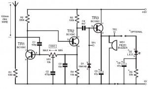
This DIY lightning detector circuit is a very sensitive static electricity detector that can provide an early warning of approaching storms from inter-cloud discharge well before an earth-to-sky return strike takes place. An aerial (antenna) formed of a short length of wire detects storms within a two mile radius.The circuit emits an audible warning tone from a piezo buzzer, or flashes an LED for each discharge detected, giving you advance warning of impendig storms so that precautions may be observed. The primary feature in the lighting detector is the circuit’s ability to be set close to self-oscillation, with its relaxation optimised via the bias resistor values shown in the circuit diagram. The oscillator is dc coupled and feedback is routed through the collector of TR1 to the base of TR2, while the overall loop gain is set with the multiturn(12, 18 or 22) preset VR1.
Lightning detector setting upTo set up the lightning sensor, adjust preset VR1 for oscillation by monitoring test point TP1, which should be at roughly 7volts peak-to-peak. Test point TP2 should be at +6V dc. Now readjust VR1 back slightly to stop oscillation; use a screwdriver to touch the aerial-side of C1 several times; the alarm should sound for 1 or 2 seconds then stop. If it continues, make a very small adjustment back and recheck. The other method is to electrostatically charge a plastic ruler and then draw your finger close to discharge, about two meter away from the aerial.
Lightning detector schematic
Reprinted Url Of This Article:
http://www.seekic.com/circuit_diagram/Measuring_and_Test_Circuit/Lightning_detector_circuit.html
Print this Page | Comments | Reading(3)

Article Categories
power supply circuit
Amplifier Circuit
Basic Circuit
LED and Light Circuit
Sensor Circuit
Signal Processing
Electrical Equipment Circuit
Control Circuit
Remote Control Circuit
A/D-D/A Converter Circuit
Audio Circuit
Measuring and Test Circuit
Communication Circuit
Computer-Related Circuit
555 Circuit
Automotive Circuit
Repairing Circuit
Code: