Measuring and Test Circuit
LOW_BATTERY_MONITOR
Published:2009/7/14 2:12:00 Author:May | From:SeekIC

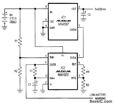
This circuit gives an early warning of declining battery voltage. Then, to allow a controlling processor time for emergency housekeeping chores, such as the storage of register data, the circuit delays system shutdown by a specified time interval (rather than waiting for battery voltage to decline further, to a specified lower level). Circuit components are chosen for low quiescent current, which protects discharged cells by minimizing the battery drain during shutdown: IC1 draws 1 μA, IC2 draws 3 μA, and R1 and R2 draw 3 μA, for a total shutdown current of about 7 μA. R1 and R3=1 MΩ, R2 =280 kΩ, R4=49.9 kΩ, R5=2.4 MΩ, and C1=3.9 μF
Reprinted Url Of This Article:
http://www.seekic.com/circuit_diagram/Measuring_and_Test_Circuit/LOW_BATTERY_MONITOR.html
Print this Page | Comments | Reading(3)

Article Categories
power supply circuit
Amplifier Circuit
Basic Circuit
LED and Light Circuit
Sensor Circuit
Signal Processing
Electrical Equipment Circuit
Control Circuit
Remote Control Circuit
A/D-D/A Converter Circuit
Audio Circuit
Measuring and Test Circuit
Communication Circuit
Computer-Related Circuit
555 Circuit
Automotive Circuit
Repairing Circuit
Code: