Measuring and Test Circuit
LIGHT_METER
Published:2009/6/17 21:49:00 Author:May | From:SeekIC

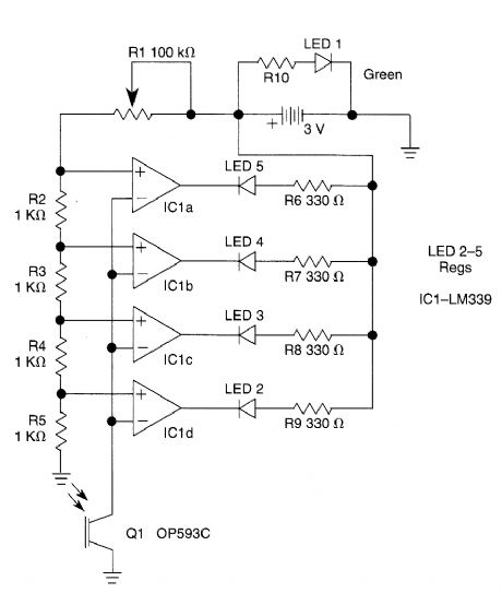
The outputs from the comparators will swing, in sequence, from high to low as the input voltage rises above the reference voltage applied to each comparator. The output LEDs will then switch on in sequence as the voltage rises.The inverting inputs of the comparators are connected in common to the collector of photo-transistor Q1. When Q1 is illuminated, its collec-tor-emitter junction conducts, thereby placing all the inverting inputs within a few millivolts of ground. For most settings of RI, each of the four reference voltages exceeds the value. Therefore, when Q1 is illuminated, the output from each comparator is high and its respective indicator LED is off.
Reprinted Url Of This Article:
http://www.seekic.com/circuit_diagram/Measuring_and_Test_Circuit/LIGHT_METER.html
Print this Page | Comments | Reading(3)

Article Categories
power supply circuit
Amplifier Circuit
Basic Circuit
LED and Light Circuit
Sensor Circuit
Signal Processing
Electrical Equipment Circuit
Control Circuit
Remote Control Circuit
A/D-D/A Converter Circuit
Audio Circuit
Measuring and Test Circuit
Communication Circuit
Computer-Related Circuit
555 Circuit
Automotive Circuit
Repairing Circuit
Code: