Measuring and Test Circuit
LED_TEST_CIRCUIT
Published:2009/7/16 20:45:00 Author:Jessie | From:SeekIC


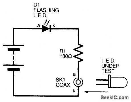
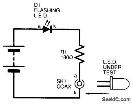
The circuit is intended as a simple one to enable spot testing of bulk surplus LEDs. A flashing LED is used (D1) with a 9-V battery, and is connected to a coaxial socket. When a test LED is placed across the socket (anode to the inner conductor), both the flashing LED and the test LED will flash. No on-off switch is necessary
Reprinted Url Of This Article:
http://www.seekic.com/circuit_diagram/Measuring_and_Test_Circuit/LED_TEST_CIRCUIT.html
Print this Page | Comments | Reading(3)

Article Categories
power supply circuit
Amplifier Circuit
Basic Circuit
LED and Light Circuit
Sensor Circuit
Signal Processing
Electrical Equipment Circuit
Control Circuit
Remote Control Circuit
A/D-D/A Converter Circuit
Audio Circuit
Measuring and Test Circuit
Communication Circuit
Computer-Related Circuit
555 Circuit
Automotive Circuit
Repairing Circuit
Code: