Measuring and Test Circuit
Infrared detector with PID20
Published:2012/9/20 20:58:00 Author:Ecco | Keyword: Infrared detector | From:SeekIC

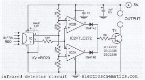
This infrared detector circuit uses a passive IR-detector component PID20. It converts heat radiation into electrical impulses. The output voltage of the PID20 increases when an object comes close to it, this object must be warmer than the surroundings.The voltage changes at the output of the IR sensor are sensed by the comparators IC2a and IC2b. Once the sensor detects an object (independent of the object’s actual temperature), one of the comparators will turn on the transistor T1. This transistor then closes the relay connected to it. A separate transistor for each comparator can be used so that the sensor will be able to determine whether the object is warmer or colder than the surroundings. The IR detector circuit consumes around 1 mA and the sensor consumes 0.2 mA.
IR detector circuit diagram
Source: electroschematics.com?
One Response to “Infrared detector with PID20”
Reprinted Url Of This Article:
http://www.seekic.com/circuit_diagram/Measuring_and_Test_Circuit/Infrared_detector_with_PID20.html
Print this Page | Comments | Reading(3)

Article Categories
power supply circuit
Amplifier Circuit
Basic Circuit
LED and Light Circuit
Sensor Circuit
Signal Processing
Electrical Equipment Circuit
Control Circuit
Remote Control Circuit
A/D-D/A Converter Circuit
Audio Circuit
Measuring and Test Circuit
Communication Circuit
Computer-Related Circuit
555 Circuit
Automotive Circuit
Repairing Circuit
Code: