Measuring and Test Circuit
INFRARED_REMOTE_CONTROL_TESTER
Published:2009/6/16 22:20:00 Author:May | From:SeekIC

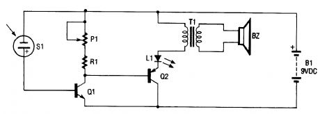
The infrared remote-control tester uses a sensitive PN-type solar sensor that is connected directly to a Darlington amplifier made up of transistors Q1 and Q2. Biasing is provided by RI and Pl, a variable resistor that serves as a sensitivity control. The collector lead of Q1 is the output lead of the Darlington amp, and it is connected to a red LED and the primary of transformer T1. The func-tion of T1 is to convert the low-voltage output signal to a level high enough to drive a small piezo disc.That disc makes a clicking sound when the sensor picks up an infrared signal that is varying in fre-quency or amplitude. The infrared sensor will also pick up visible light. The use of an IR filter (Wrat-ton #87) is recommended.
BZ Piezo DiscL1 Jumbo Red LEDP1 2-MΩ Trimmer Resistor Q1 2N3904 TransistorQ2 2N3906 TransistorR1 270-Ω ResistorS1 Solar SensorT1 Audio Transformer
Reprinted Url Of This Article:
http://www.seekic.com/circuit_diagram/Measuring_and_Test_Circuit/InfraRed_Remote_Control_Tester.html
Print this Page | Comments | Reading(3)

Article Categories
power supply circuit
Amplifier Circuit
Basic Circuit
LED and Light Circuit
Sensor Circuit
Signal Processing
Electrical Equipment Circuit
Control Circuit
Remote Control Circuit
A/D-D/A Converter Circuit
Audio Circuit
Measuring and Test Circuit
Communication Circuit
Computer-Related Circuit
555 Circuit
Automotive Circuit
Repairing Circuit
Code: