Measuring and Test Circuit
How to build Economy radar detector
Published:2012/10/18 3:22:00 Author:muriel | Keyword: Economy, radar, detector | From:SeekIC

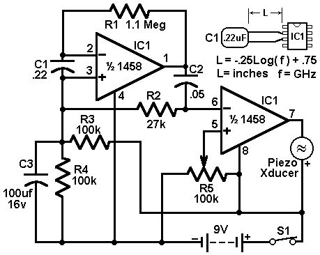
This circuit uses a 1458 dual op-amp to form a radar detector. C1 is the detector of the radar signal. The first op-amp forms a current-to-voltage converter and the second op-amp buffers the output to drive the piezo transducer. R5 sets the switching threshold of the second op-amp; normally it is adjusted so that the circuit barely triggers on background noise, then it's backed off a bit. The response of the circuit may be tuned by adjusting the length of the leads on C1. For typical road-radar systems, the input capacitor's leads should be about 0.5 to 0.6 inches long.
Reprinted Url Of This Article:
http://www.seekic.com/circuit_diagram/Measuring_and_Test_Circuit/How_to_build_Economy_radar_detector.html
Print this Page | Comments | Reading(3)

Article Categories
power supply circuit
Amplifier Circuit
Basic Circuit
LED and Light Circuit
Sensor Circuit
Signal Processing
Electrical Equipment Circuit
Control Circuit
Remote Control Circuit
A/D-D/A Converter Circuit
Audio Circuit
Measuring and Test Circuit
Communication Circuit
Computer-Related Circuit
555 Circuit
Automotive Circuit
Repairing Circuit
Code: