Measuring and Test Circuit
GEIGER_COUNTER_CIRCUIT
Published:2009/7/14 2:13:00 Author:May | From:SeekIC

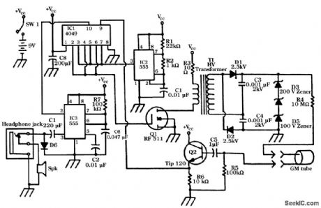
IC2 is a 555 timer set in astable mode. The signal from IC2 is presented to three gates on the 4049 IC1. The 4049 inverts the signal to give an optimum pulse width that switches Q1 on and off. The MOSFET(Q1),in turn,switches the current to a step-up transformer(T1). The stepped-up voltage from T1 first passes through a voltage doubler; the output voltage from this section is approxtmatety 600 to 700 V . Three zener diodes(D3,D4,and D5)are placed across the output of the voltage doubler to regulate the voltage to 500 V. This voltage is connected to the anode on the GM tube through a 10-MΩ resistor. When the GM tube detects a particle,a voltage pulse from the 100-kΩ resistor is amplified and clamped to VCC, Via Q2,an NPN Darlington transistor. The signal from Q2 is inverted by IC1,where it acts as a trigger signal to IC3. IC3 is another 555 timer. The output of IC3 Via pin 3 flashes on LED and provides a click into either the speaker or the headphones . The circuit is powered by a 9-V alkaline battery and draws about 28 mA when not detecting.
Reprinted Url Of This Article:
http://www.seekic.com/circuit_diagram/Measuring_and_Test_Circuit/GEIGER_COUNTER_CIRCUIT.html
Print this Page | Comments | Reading(3)

Article Categories
power supply circuit
Amplifier Circuit
Basic Circuit
LED and Light Circuit
Sensor Circuit
Signal Processing
Electrical Equipment Circuit
Control Circuit
Remote Control Circuit
A/D-D/A Converter Circuit
Audio Circuit
Measuring and Test Circuit
Communication Circuit
Computer-Related Circuit
555 Circuit
Automotive Circuit
Repairing Circuit
Code: