Measuring and Test Circuit
FREQUENCY_COUNTER
Published:2009/7/9 22:59:00 Author:May | From:SeekIC

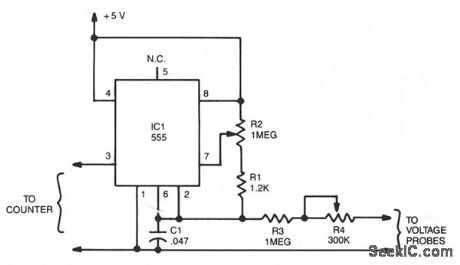
The output frequency from IC pin 3 is determined by the voltage input to pin 6. A standard frequency counter can be used to measure voltages directly over a limited range from 0 to 5 V. In this circuit, the 555 is wired as an astable multi ibrator. Resistor R2 determines the output frequency when the input to the circuit (the voltage measured by the voltage probes) is zero. R4 is a scaling resistor that adjusts the output frequency so that a change in the input voltage of 1 V will result in a change in the output frequency of 10 Hz. That will happen when the combined resistance of R3 and R4 is 1.2 MΩ. To calibrate short the voltage probes together, adjust R2 until the reading on the frequency counter changes to 00 Hz. Then, use the voltage probes to measure an accurate 5-V source and adjust R4 until the frequency counter reads 50 Hz.
Reprinted Url Of This Article:
http://www.seekic.com/circuit_diagram/Measuring_and_Test_Circuit/FREQUENCY_COUNTER.html
Print this Page | Comments | Reading(3)

Article Categories
power supply circuit
Amplifier Circuit
Basic Circuit
LED and Light Circuit
Sensor Circuit
Signal Processing
Electrical Equipment Circuit
Control Circuit
Remote Control Circuit
A/D-D/A Converter Circuit
Audio Circuit
Measuring and Test Circuit
Communication Circuit
Computer-Related Circuit
555 Circuit
Automotive Circuit
Repairing Circuit
Code: