Measuring and Test Circuit
FLASH_BATTERY_TESTER
Published:2009/7/14 1:47:00 Author:May | From:SeekIC

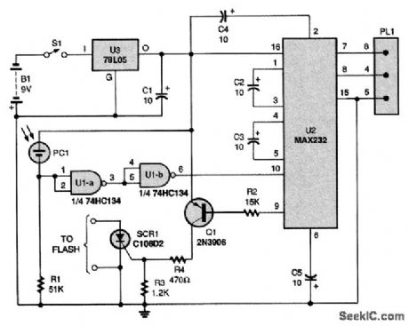
Power from a 9-V battery (B1) is fed to a 78L05 regulator (U3). The IC then produces a regulated 5 V to power the rest of the circuit. A cadmium sulfide photocell, PC1, conducts when a connected flash's ready light comes on and illuminates it. When current flows through PC1, U1-a, and U1-b, two sections of a 74HC134 quad Schmitt trigger NAND gate produce a sharp-edged TTL high. A MAX232, U2, converts the high to an RS233 low that is compatible with the PC's serial port. The MAX232 also takes an incoming serial-port pulse and converts it to TTL levels to fire the flash via SCR1, a C106D2 silicon-controlled rectifier. The circuit works with a BASIC program. That program fires the flash by sending a brief pulse through plug PL1 to the serial port's DTR pin. The program then starts timing how long it takes for the flash to recycle. In other words, the program 'looks at the CTS pin over and over until it sees that it went low. That happens when the photocell is lit by the flash's ready light. The program records the elapsed time and continues counting until 1 minute elapses. At that time, the DTR pin is cycled again to fire the flash, and the process is repeated. The test concludes when the recycle time exceeds 45 seconds.
Reprinted Url Of This Article:
http://www.seekic.com/circuit_diagram/Measuring_and_Test_Circuit/FLASH_BATTERY_TESTER.html
Print this Page | Comments | Reading(3)

Article Categories
power supply circuit
Amplifier Circuit
Basic Circuit
LED and Light Circuit
Sensor Circuit
Signal Processing
Electrical Equipment Circuit
Control Circuit
Remote Control Circuit
A/D-D/A Converter Circuit
Audio Circuit
Measuring and Test Circuit
Communication Circuit
Computer-Related Circuit
555 Circuit
Automotive Circuit
Repairing Circuit
Code: