Measuring and Test Circuit
EXPANDED_SCALE_ANALOG_METER
Published:2009/7/9 23:38:00 Author:May | From:SeekIC

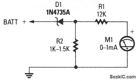
The circuit consists of 0-1 mA meter M1, 6.2-V zener diode D1, and 12-KΩ, 1% resistor R1. R2 is included in the circuit as a load resistor for the zener diode. The value of R2 isn't critical; use a value of 1000 to 1500 Ω. The meter reads from 6 to 18 volts, which is perfect for checking a car's charging system.
Reprinted Url Of This Article:
http://www.seekic.com/circuit_diagram/Measuring_and_Test_Circuit/EXPANDED_SCALE_ANALOG_METER.html
Print this Page | Comments | Reading(3)

Article Categories
power supply circuit
Amplifier Circuit
Basic Circuit
LED and Light Circuit
Sensor Circuit
Signal Processing
Electrical Equipment Circuit
Control Circuit
Remote Control Circuit
A/D-D/A Converter Circuit
Audio Circuit
Measuring and Test Circuit
Communication Circuit
Computer-Related Circuit
555 Circuit
Automotive Circuit
Repairing Circuit
Code: