Measuring and Test Circuit
Current-Flowing-Direction Demonstrator Circuit Diagram
Published:2011/7/7 8:27:00 Author:Vicky | Keyword: Current-Flowing-Direction Demonstrator | From:SeekIC


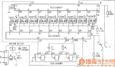
The circuit in the first picture adopts a transistor VT as input signal amplifier. VT is also used to drive a relay K. It drives the reset mode of pulse output circuit IC1& IC2’s reset end R by the changing of the relay’s contact, and thereby changes the lightening state of two-color luminous diodes to indicate the different flowing direction of the current.
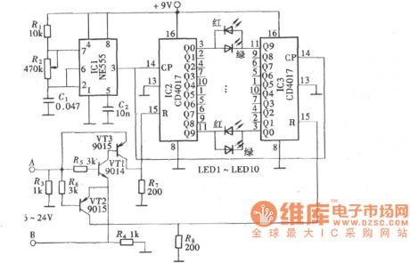
The second picture is an analog demonstrating conducted by a little instrument made of CMOS digital circuit. The circuit used decimal counter/pulse distributor CD4017, together with two-color luminous diode (the colors are red and green) to constitute a analog current-flowing-direction demonstrator.
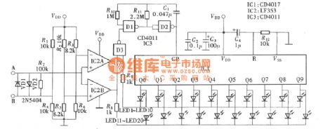
The circuit in the third picture uses work power voltage of 6V. If the work voltage needs to be changed, the resistance value of the resistance network should be re-calculated and the voltage of end R6 is 0.5V and must be lower than the voltage drop of VD2; the voltage of upper end of R5 is 0.5 and must be lower the voltage drop of VD1.
Reprinted Url Of This Article:
http://www.seekic.com/circuit_diagram/Measuring_and_Test_Circuit/Current_Flowing_Direction_Demonstrator_Circuit_Diagram.html
Print this Page | Comments | Reading(3)

Article Categories
power supply circuit
Amplifier Circuit
Basic Circuit
LED and Light Circuit
Sensor Circuit
Signal Processing
Electrical Equipment Circuit
Control Circuit
Remote Control Circuit
A/D-D/A Converter Circuit
Audio Circuit
Measuring and Test Circuit
Communication Circuit
Computer-Related Circuit
555 Circuit
Automotive Circuit
Repairing Circuit
Code: