Measuring and Test Circuit
CURRENT_LIMITERS
Published:2009/7/13 2:23:00 Author:May | From:SeekIC


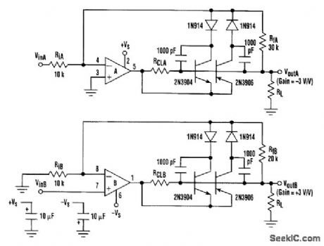
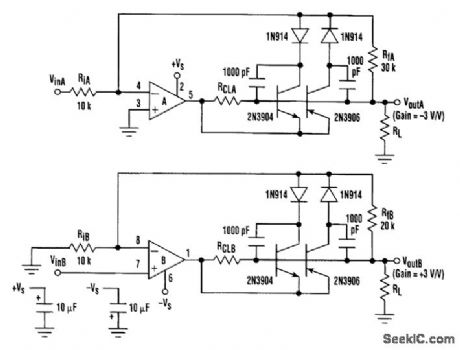
A user-controlled internal current limit on power op amps isn't always provided by manufacturers. However, the current limit can be set extemally by using the technique shown, in which the output current is sensed with a single resistor. The resistor activates a complementary transistor switch that reduces irtverting gain, lirrtiting output current. The technique is demonstrated with 8-pin OPA2541 or OPA2544 dual-power op amps that are lacking an intemal user-controlled current limit. The extemal components add an adjustable current limit to these amplifiers. The PNP transistor controls the positive current limit, and the NPN transistor controls the negative current limit. Both transistors are 0FF until the voltage drop across RCT reaches the current-limit set point. At the current-limit set point, current from the controlling transistor will sum with the input current (through Ri) at the op amp's inverting input summing junction. This will limit the output. The diodes in series with the collectors of both transistors prevent forward base-collector bias. High-frequency oscillation during current limit is damped out with the 1000-pF capacitors. These capacitors only nominally affect the conftguration's closed-loop bandwidth because the diodes, which are normally off, isolate them.
Reprinted Url Of This Article:
http://www.seekic.com/circuit_diagram/Measuring_and_Test_Circuit/CURRENT_LIMITERS.html
Print this Page | Comments | Reading(3)

Article Categories
power supply circuit
Amplifier Circuit
Basic Circuit
LED and Light Circuit
Sensor Circuit
Signal Processing
Electrical Equipment Circuit
Control Circuit
Remote Control Circuit
A/D-D/A Converter Circuit
Audio Circuit
Measuring and Test Circuit
Communication Circuit
Computer-Related Circuit
555 Circuit
Automotive Circuit
Repairing Circuit
Code: