Measuring and Test Circuit
CLOSED_LOOP_PEAK_DETECTOR
Published:2009/6/15 22:33:00 Author:May | From:SeekIC

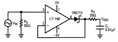
This closed-loop peak detector circuit uses a Schottky diode inside feedback loop to obtain good accuracy. The 20-Ω resistance R, isolates the 0.01-μF load and prevents oscillation. The dc value is read with a DVM. At a low frequency, the error is small and dominated by the decay of the detector capacitor between cycles. As the frequency rises, the error increases because capacitor charging time decreases. During this time, the overdrive becomes a very small portion of a sine-wave cycle. Finally, at approximately 4 MHz, the error rises rapidly because of the slew-rate lim-itation of the op amp.
Reprinted Url Of This Article:
http://www.seekic.com/circuit_diagram/Measuring_and_Test_Circuit/CLOSED_LOOP_PEAK_DETECTOR.html
Print this Page | Comments | Reading(3)

Article Categories
power supply circuit
Amplifier Circuit
Basic Circuit
LED and Light Circuit
Sensor Circuit
Signal Processing
Electrical Equipment Circuit
Control Circuit
Remote Control Circuit
A/D-D/A Converter Circuit
Audio Circuit
Measuring and Test Circuit
Communication Circuit
Computer-Related Circuit
555 Circuit
Automotive Circuit
Repairing Circuit
Code: