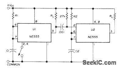
Measuring and Test Circuit
CASCADED_TIMER
Published:2009/7/12 21:34:00 Author:May | From:SeekIC

Two NE555 timers give sequential timing intervals for two separate loads.Time for U1 is set by R1 and C1, and for U2 by R2 and C2. Grounding pin 2 momentarily with switch starts timing. Once started, it cannot be retriggered. With pin 2 connected to reset input 4, both functions are obtained with one push of switch, lf reset function is not wanted, connect 4 to 8. When pin 3 of U1 goes low at end of timing interval, negative pulse generated by 0.001-μF capacitor and 27K resistor goes to pin 2 of U2 to trigger second timer. With 15-V supply, each timer can handle 200-mA load.-H. Vordenbaum, Automatic Reset Timer, Ham Radio, Oct. 1974, p 50-51.
Reprinted Url Of This Article:
http://www.seekic.com/circuit_diagram/Measuring_and_Test_Circuit/CASCADED_TIMER.html
Print this Page | Comments | Reading(3)

Article Categories
power supply circuit
Amplifier Circuit
Basic Circuit
LED and Light Circuit
Sensor Circuit
Signal Processing
Electrical Equipment Circuit
Control Circuit
Remote Control Circuit
A/D-D/A Converter Circuit
Audio Circuit
Measuring and Test Circuit
Communication Circuit
Computer-Related Circuit
555 Circuit
Automotive Circuit
Repairing Circuit
Code: