Measuring and Test Circuit
CAPACITOR_CHECKER
Published:2009/7/16 1:39:00 Author:Jessie | From:SeekIC

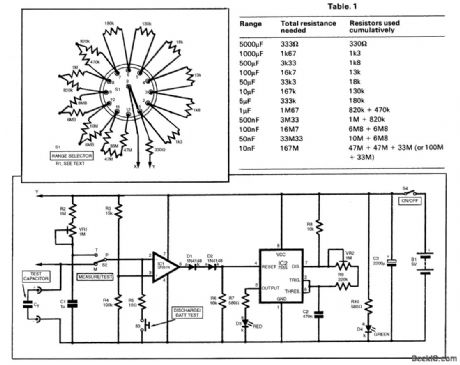
The circuit for the capacitor checker is shown in the figure. Switch S2 is used to select the Mea-sure (M) or Test (T) mode, as required. Assume for the moment that it is in the M position, as shown. Operational amplifier IC1 is configured as a voltage comparator. The values of the resistors have been chosen to provide 86 percent (actually, it is nearer 87 percent) of the supply voltage to the noninverting input, pin 3. Meanwhile, the capacitor being measured, Ct, charges through resistor R1, so the voltage across it rises and follows the form shown in Fig. 2.R1 is selected from a chain of resistors using the rotary range switch, S1 (inset). The value of R1 in the chain will be such that with a capacitor at the top of the range selected (e.g.a100-nF capacitor on the 100-nF range), the time constant will be 1.66 s. The values of R1, required to provide this time constant on the various ranges are shown in Table 1. Assuming that the test capacitor Ct is discharged to begin with, after two time constants have elapsed, the voltage across the capacitor will rise above 86 percent of the supply. The op amp switches off, with pin 6 becoming low. While IC1 pin 6 is high (during the initial stages of C, charging), IC2 pin 4 is maintained in a high state, which enables the IC. When the capacitor charges through two time constants, IC1 pin 6 becomes low, IC2 is disabled, and the flashing stops. The nominally low state of IC1 output would still be high enough to enable IC2 if connected directly, and the two diodes (D1 and D2) correct this. Resistor R6 maintains IC2 pin 4 low in the absence of a high state from IC1 output. The rate at which pulses are produced depends on the values of fixed resistors R8 and R9 and preset potentiometer VR2, in conjunction with capacitor C2. With the values chosen, they will be delivered at between 1 and 10 per second approximately, depending on the adjustment of VR2. VR2 will be adjusted so that exactly three flashes per second are provided. Ten flashes, therefore, correspond to 3.33 s, which is equal to two time constants for a capacitor at the limit of the range selected.
Reprinted Url Of This Article:
http://www.seekic.com/circuit_diagram/Measuring_and_Test_Circuit/CAPACITOR_CHECKER.html
Print this Page | Comments | Reading(3)

Article Categories
power supply circuit
Amplifier Circuit
Basic Circuit
LED and Light Circuit
Sensor Circuit
Signal Processing
Electrical Equipment Circuit
Control Circuit
Remote Control Circuit
A/D-D/A Converter Circuit
Audio Circuit
Measuring and Test Circuit
Communication Circuit
Computer-Related Circuit
555 Circuit
Automotive Circuit
Repairing Circuit
Code: