Measuring and Test Circuit
CAPACITANCE_TO_VOLTAGE_METER
Published:2009/7/6 5:09:00 Author:May | From:SeekIC
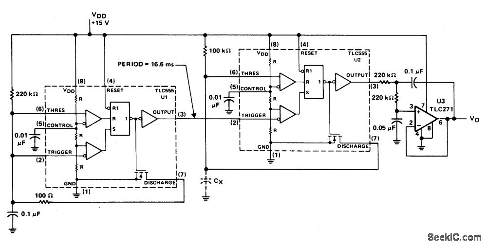
Timer U1 operates as a free-running oscillator at 60 Hz, providing trigger pulses to timer U2 which operates in the monostable mode. Resistor R1 is fixed and capacitor Cx is the capacitor being measured. While the output of U2 is 60 Hz, the duty cycle depends on the value of Cx. U3 is a combination low-pass filter and unity-gain follower whose dc voltage output is the time-averaged amplitude of the output pulses of U2, as shown in the timing diagram.
The diagram shows when the value of Cx is small the duty cycle is relatively low. The output pulses are narrow and produce a lower average dc voltage level at the output of U3. As the capacitance value of Ox increases, the duty cycle increases making the output pulses at U2 wider and the average dc level output at U3 increases. The graph illustrates capacitance values of 0.01 pF to 0.1 μF plotted against the output voltage of U3. Notice the excellent linearity and direct one-to-one scale calibration of the meter. If this does not occur the 100 k ohm resistor, R1, can be replaced with a potentiometer which can be adjusted to the proper value for the meter being used.
Reprinted Url Of This Article:
http://www.seekic.com/circuit_diagram/Measuring_and_Test_Circuit/CAPACITANCE_TO_VOLTAGE_METER.html
Print this Page | Comments | Reading(3)

Article Categories
power supply circuit
Amplifier Circuit
Basic Circuit
LED and Light Circuit
Sensor Circuit
Signal Processing
Electrical Equipment Circuit
Control Circuit
Remote Control Circuit
A/D-D/A Converter Circuit
Audio Circuit
Measuring and Test Circuit
Communication Circuit
Computer-Related Circuit
555 Circuit
Automotive Circuit
Repairing Circuit
Code: