Measuring and Test Circuit
CABLE_TESTER_RECEIVER
Published:2009/7/15 23:31:00 Author:Jessie | From:SeekIC

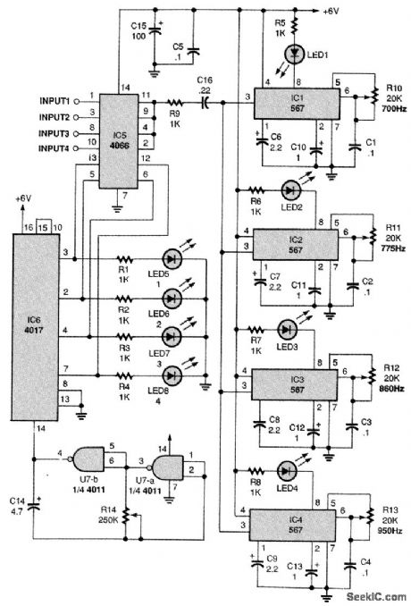
The four inputs are connected to four input contacts of a quad bilateral switch, IC5, with the out-put contacts tied together and connected to the inputs of the 567 decoders through R9 and C16. The bilateral switch's four control inputs are operated by IC6, a 4017 decade counter IC, which is driven by a low-frequency oscillator made up of two gates of IC7, a quad two-input NAND gate. Four LEDs, LED 5 through LED8, are connected to IC6's four outputs and indicate which input is being checked, just as in manual mode. When LED5 is on, input 1 is switched through to the four decoder circuits. The decoder that responds, by lighting its LED, indicates which output-700, 775, 880, or 950 Hz-is connected to that input. Resistor R14 sets the input-stepping rate, which should be slow enough for recording.
Reprinted Url Of This Article:
http://www.seekic.com/circuit_diagram/Measuring_and_Test_Circuit/CABLE_TESTER_RECEIVER.html
Print this Page | Comments | Reading(3)

Article Categories
power supply circuit
Amplifier Circuit
Basic Circuit
LED and Light Circuit
Sensor Circuit
Signal Processing
Electrical Equipment Circuit
Control Circuit
Remote Control Circuit
A/D-D/A Converter Circuit
Audio Circuit
Measuring and Test Circuit
Communication Circuit
Computer-Related Circuit
555 Circuit
Automotive Circuit
Repairing Circuit
Code: