Measuring and Test Circuit
CABLE_SHORT_DETECTOR
Published:2009/7/15 23:34:00 Author:Jessie | From:SeekIC

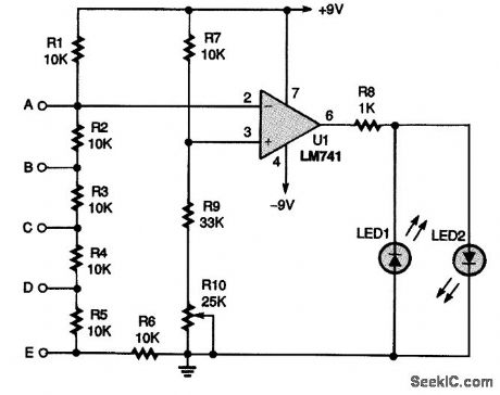
A five-input short-detector circuit can be used to check long runs of a two- to five-wire cable for shorts between any of the wires. An LM741 op-amp IC, U1, is connected in a comparator circuit. The inverting input (pin 2) of U1 is connected to a +9-V source and a series of six resistors, while the noninverting input (pin 3) of the op amp is connected to an adjustable voltage-divider circuit. To use the circuit, potentiometer R10 should be used to set the voltage at pin 3 to a slightly more negative voltage than that at pin 2; U1's output will swing low, lighting LED1. Make that adjustment slowly until LED1 just barely turns on. Then connect one end of a cable to points A to E. When any of resistors R2 to R6 are shorted out, the voltage at pin 2 will go negative with respect to pin 3. That will make the op amp's output go positive, which will light LED2, indicating a short in the cable.
Reprinted Url Of This Article:
http://www.seekic.com/circuit_diagram/Measuring_and_Test_Circuit/CABLE_SHORT_DETECTOR.html
Print this Page | Comments | Reading(3)

Article Categories
power supply circuit
Amplifier Circuit
Basic Circuit
LED and Light Circuit
Sensor Circuit
Signal Processing
Electrical Equipment Circuit
Control Circuit
Remote Control Circuit
A/D-D/A Converter Circuit
Audio Circuit
Measuring and Test Circuit
Communication Circuit
Computer-Related Circuit
555 Circuit
Automotive Circuit
Repairing Circuit
Code: