Measuring and Test Circuit
Bearing fault detector 2
Published:2011/6/24 7:57:00 Author:Nicole | Keyword: bearing fault, detector | From:SeekIC

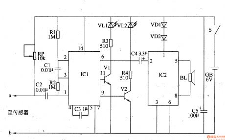
The bearing fault detector circuit is composed of bearing testing sensor, signal process circuit and acousto-optic circuit, it is shown in the figure 8-79.
The signal process circuit is made of input socket XS, sound control integrated circuit IC1, capacitors C1-C3, resistors R1, R2 and potentiometer RP.
The acousto-optic circuit consists of transistors V1, V2, LED VL1, VL2, audio power amplifier integrated circuit IC2, resistors R3, R4, capacitor C4, diode VD1, VD2 and loudspeaker BL.
The sensor's sensitivity can be changed by adjusting RP.
Reprinted Url Of This Article:
http://www.seekic.com/circuit_diagram/Measuring_and_Test_Circuit/Bearing_fault_detector_2.html
Print this Page | Comments | Reading(3)

Article Categories
power supply circuit
Amplifier Circuit
Basic Circuit
LED and Light Circuit
Sensor Circuit
Signal Processing
Electrical Equipment Circuit
Control Circuit
Remote Control Circuit
A/D-D/A Converter Circuit
Audio Circuit
Measuring and Test Circuit
Communication Circuit
Computer-Related Circuit
555 Circuit
Automotive Circuit
Repairing Circuit
Code: