Measuring and Test Circuit
Bearing fault detector 1
Published:2011/6/24 7:48:00 Author:Nicole | Keyword: bearing fault, detector | From:SeekIC

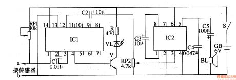
The bearing fault detector circuit is composed of bearing testing sensor, signal process circuit IC1, LED VL, transistor V, audio amplifier integrated circuit IC2, soudspeaker BL and some relevant resistor capacitor components, it is shown in the figure 8-78.
After the power supply switch S is turned on, IC1 works, its 4 foot and 12 foot all output high level, V is turned on, VL is lighted, then IC2's 3 foot has no input signal, loudspeaker BL does not phonate.
RP1 is used to adjust the sensitivity of signal process circuit.
RP2 is used to regulate the loudspeaker's output volume.
Reprinted Url Of This Article:
http://www.seekic.com/circuit_diagram/Measuring_and_Test_Circuit/Bearing_fault_detector_1.html
Print this Page | Comments | Reading(3)

Article Categories
power supply circuit
Amplifier Circuit
Basic Circuit
LED and Light Circuit
Sensor Circuit
Signal Processing
Electrical Equipment Circuit
Control Circuit
Remote Control Circuit
A/D-D/A Converter Circuit
Audio Circuit
Measuring and Test Circuit
Communication Circuit
Computer-Related Circuit
555 Circuit
Automotive Circuit
Repairing Circuit
Code: