Measuring and Test Circuit
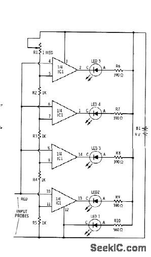
BAR_GRAPH_READOUT_VOLTMETER
Published:2009/7/14 23:38:00 Author:Jessie | From:SeekIC

Sections of RS339 quad comparator each drive LED to give indications of four different input voltage levels, While LED 1 is connected to ground for use as zero indicator Resistors shown are for Radio Shack 276-041 red LEDs;change R6-R9 to 270 ohms and R1 to 470 ohms for green LEDs Pot R1 is used to calibrate voltage divider R2-R5 With R1 set allow resistance, comparators turn on at intervals of 1 V or more,With high resistance for R1, comparators turn on at fractional-volt intervals. –F. M. Mims,” Integrated Circuit Projects, vol. 4,” Radio Shack, Fort Worth, TX, 1977, 2 nd Ed., ρ76-85.
Reprinted Url Of This Article:
http://www.seekic.com/circuit_diagram/Measuring_and_Test_Circuit/BAR_GRAPH_READOUT_VOLTMETER.html
Print this Page | Comments | Reading(3)

Article Categories
power supply circuit
Amplifier Circuit
Basic Circuit
LED and Light Circuit
Sensor Circuit
Signal Processing
Electrical Equipment Circuit
Control Circuit
Remote Control Circuit
A/D-D/A Converter Circuit
Audio Circuit
Measuring and Test Circuit
Communication Circuit
Computer-Related Circuit
555 Circuit
Automotive Circuit
Repairing Circuit
Code: