Measuring and Test Circuit
A part of product detector circuit composed of LF198 and LM122H
Published:2012/8/23 22:27:00 Author:Ecco | Keyword: product detector | From:SeekIC
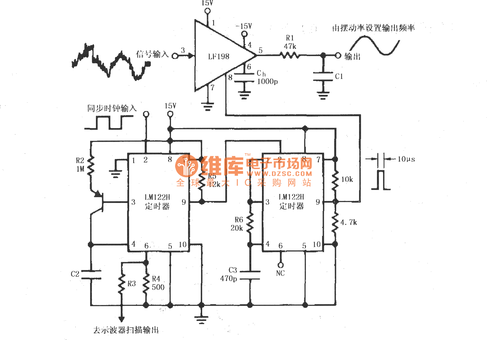
Synchronous clock signal is input to a cascade of timer circuit composed of two LM122H, then the synchronization clock is converted to the desired width of the pulse (Fig. 10μs) which will be add to LF198 LOGIC end (8 feet) as the sampling and holding control signal . The signal is input LF198's pin 3. The input signal contains a large number of noise component with magnitude higher than the useful signal, after the detector, the output signal's noise is filtered off, a pure signal will be output. The value of R3 should make 6-pin voltage be 0 ~~ 3V.
Reprinted Url Of This Article:
http://www.seekic.com/circuit_diagram/Measuring_and_Test_Circuit/A_part_of_product_detector_circuit_composed_of_LF198_and_LM122H.html
Print this Page | Comments | Reading(3)

Article Categories
power supply circuit
Amplifier Circuit
Basic Circuit
LED and Light Circuit
Sensor Circuit
Signal Processing
Electrical Equipment Circuit
Control Circuit
Remote Control Circuit
A/D-D/A Converter Circuit
Audio Circuit
Measuring and Test Circuit
Communication Circuit
Computer-Related Circuit
555 Circuit
Automotive Circuit
Repairing Circuit
Code: